Great things in business are never done by one person. They’re done by a team of people. We have that dynamic group of peoples
This article dives deep into the world of interfacing a 16×2 LCD module with microcontrollers like Arduino and ESP32, specifically focusing on the setup without using an I2C module. We’ll explore why you might choose this method, how it works, and provide a detailed tutorial for connecting and programming your LCD. If you’re looking to understand the fundamentals of LCD interfacing and how to drive a 16×2 lcd display without relying on the convenience of an I2C adapter, this is the guide for you.
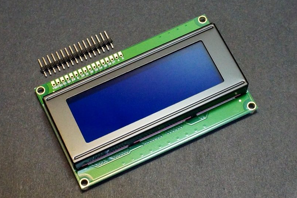
A 16×2 LCD display, short for a 16 character by 2 line liquid crystal display, is a common and versatile display module. It’s used to present text and numerical information in a clear and concise manner. Unlike complex graphical displays, 16×2 LCDs are relatively simple to drive, making them perfect for various microcontroller projects. The “16×2” refers to its capacity to display 16 characters on each of its two rows, making it suitable for displaying sensor readings, project status, or user messages. Interfacing these lcd display modules with microcontrollers like arduino or ESP32 allows your projects to interact with the user by displaying information in a human readable form. They are relatively cheap and easy to use.
The appeal of the 16×2 lcd module lies in its simplicity and low cost. It is a staple in electronics for various hobby and professional projects due to its ability to display text and numbers without the overhead of more complex display technologies. Interfacing this module allows embedded system developers to create devices that are able to provide visual feedback, without using complex graphical displays. The ease of integration makes 16×2 lcds a very useful display tool for displaying information from various sensors.
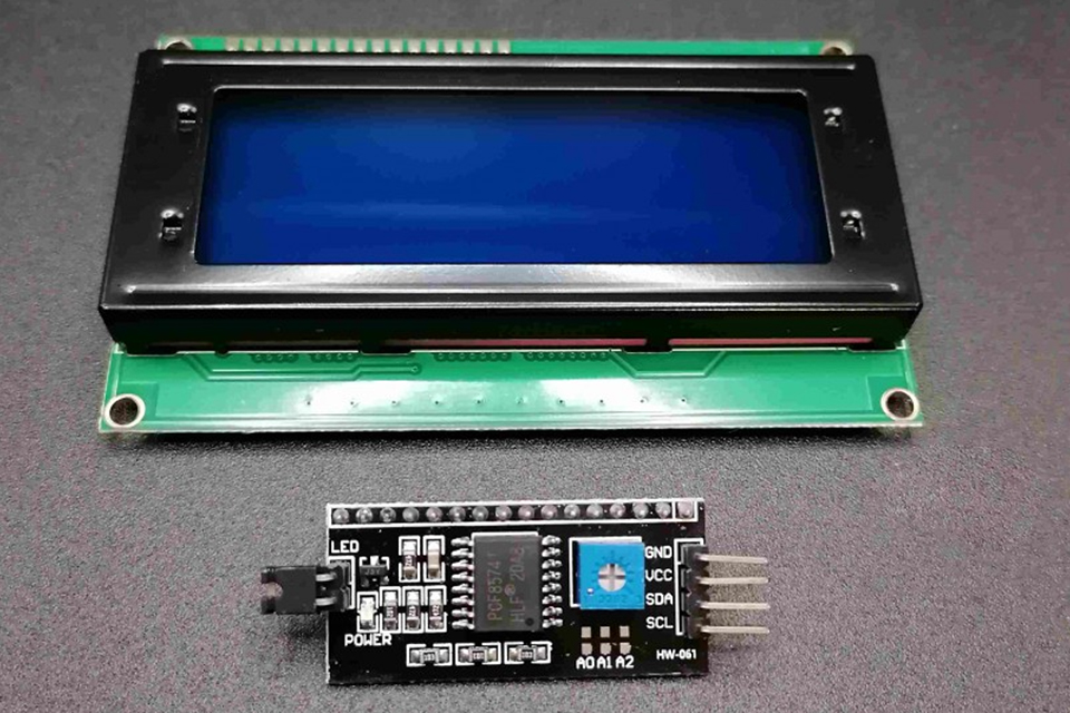
While I2C modules offer the convenience of reducing the number of pins required for interfacing, choosing to connect a 16×2 lcd without i2c directly has several advantages. First, it provides a deeper understanding of the underlying communication protocols and how the LCD module functions, making it a great educational experience. Second, by not relying on i2c interface you avoid the complexities of the i2c bus and potential address conflicts. This can be important if you’re facing limitations in your project or want to reduce the complexity of your i2c devices connection. You are not limited by one address.
Moreover, direct interfacing can be beneficial for projects where every pin on your microcontroller is valuable. An i2c module typically reduces the number of pins you have to use to 2, but these 2 pins are dedicated to i2c communication and might be needed for something else, while interfacing without an i2c module you can freely select which pins you want to use. Interfacing without an i2c module gives you full control of the connection. Direct connection can also be faster for displaying data, since i2c communication has to be performed before data can be transmitted to the lcd display. This is not always critical, but is something to consider when designing applications that require fast update times for the displayed content.
To interface a 16×2 LCD module without i2c, you’ll need a few essential components. The core item is a standard 16×2 lcd, which typically comes with 16 pins for connection. You’ll also need a microcontroller, such as an Arduino Uno, or ESP32. Additionally, you’ll need jumper wires to connect the various pins of the lcd module to your microcontroller. Furthermore, a potentiometer is necessary to adjust the contrast of the lcd display. A breadboard can be a great help to keep everything neatly connected and organized.
The key challenge when connecting a 16×2 lcd without i2c is that it requires more pins from your microcontroller than using an i2c adapter. Specifically, we will use 6 pins to control the LCD display, plus two pins to control the power supply and ground. Therefore, you should plan your microcontroller circuit with enough available output pins. Having these pins available gives you full control of the lcd. The potentiometer allows you to adjust the contrast so that the text on the lcd display is clearly visible.
The 16×2 LCD is based on the HD44780 controller or a compatible chip. This controller manages the display of characters and accepts commands through a parallel interface. The interface typically uses 8 data pins (D0-D7) or 4 data pins in 4-bit mode (D4-D7), plus control pins (RS, R/W, and EN). Each character position on the lcd display is addressed by the controller internally. When you send a command or a character data, the HD44780 controller receives the command and acts accordingly.
The HD44780 controller uses specific commands for tasks like clearing the display, setting the cursor position, or initializing the lcd. Understanding this architecture is crucial when you’re writing code to control the lcd without the abstraction provided by an i2c module. The commands are sent to the display over the data pins and the mode of communication is determined by control pins. This also allows the controller to work with different types of display sizes like 20×4, the 16×2 lcd display uses a predefined character set that can be displayed on the screen.
Connecting a 16×2 lcd directly to an Arduino involves wiring each necessary pin. First, you’ll need to connect the LCD’s VSS pin to ground (GND) and the VDD pin to 5V, this is your power supply. The V0 pin (contrast adjustment) is connected to the middle pin of the potentiometer; the other two pins of the potentiometer are connected to ground and 5v to make a voltage divider which we will use to change contrast of the lcd display. Next, connect the RS (Register Select) pin of the lcd to a digital pin of the arduino (e.g., pin 12). The R/W (Read/Write) pin should be grounded as we will only be writing data to the LCD. The EN (Enable) pin needs to be connected to another digital pin on the arduino (e.g., pin 11).
Then, connect the data pins D4 to D7 to digital pins on the arduino, for example pins 5, 4, 3, and 2 respectively. This way, we’re using the 4-bit mode, which is common practice, as it uses less pins. The 4-bit mode is simpler and uses less wiring compared to the 8-bit mode. The backlight pins A (anode) and K (cathode) should be connected to 5V and GND respectively with a current-limiting resistor on the anode if necessary. Ensure you use a circuit diagram to guide this process. The pins are sometimes numbered differently for some lcd modules. The pin layout can always be found in the lcd module datasheet.
To program your arduino to interface the 16×2 lcd, you will need to use the LiquidCrystal library. Start by opening the arduino ide and include the liquidcrystal library in your project code. Initialize the lcd object in your code, specifying the pins used for connection. In our example that is pins: RS, EN, D4, D5, D6, D7. For example: LiquidCrystal lcd(12, 11, 5, 4, 3, 2);. Inside the setup() function, initialize the lcd by calling lcd.begin(16, 2); to set the number of columns and rows of the lcd display. You should also initialize the lcd using the initialize the lcd function.
Now, in the loop function, you can use various commands to display data on the lcd display. For example, you can set the cursor position with lcd.setCursor(column, row); and display text with lcd.print("Hello World");. You can clear the display with the lcd.clear(); command. You can create a short program and ran a few codes to test the board and after i connected it all. You can use serial monitor to debug the program. The liquidcrystal library handles all of the HD44780 low-level communication for you, so you don’t have to worry about sending individual byte sequences and control signals. The key function is lcd.print() which is used to display the data.
#include <LiquidCrystal.h>

// Define pins connected to the LCD
const int rs = 12, en = 11, d4 = 5, d5 = 4, d6 = 3, d7 = 2;

// Initialize LCD object
LiquidCrystal lcd(rs, en, d4, d5, d6, d7);

void setup() {
  // Set the number of columns and rows
  lcd.begin(16, 2);
  // Print a message to the LCD
  lcd.print("Hello, LCD!");
}

void loop() {
  // Set cursor to the second line
  lcd.setCursor(0, 1);
  // Display the time
  lcd.print(millis()/1000);
  lcd.print(" seconds");
}
Interfacing a 16×2 LCD without i2c on an ESP32 is similar to doing so on an Arduino, but with some minor differences. The ESP32 is a 3.3V microcontroller, while the 16×2 lcd is typically designed to operate at 5V. Therefore, you may need to use level shifters for voltage compatibility between the ESP32 and LCD’s logic pins. Alternatively, using an esp32 board with level shifting can eliminate the need for external level shifting circuitry. The physical wiring will largely be the same as with an Arduino. Connect VSS to ground and VDD to 5V (or 3.3V if you are using a 3.3V lcd or level shifters).
The code in the arduino ide will be almost the same as the one provided for arduino with little to no changes. Use the LiquidCrystal library in the same way as in the Arduino tutorial. Remember to define your pin connections correctly in the LiquidCrystal lcd object. Always check the datasheet of your lcd module to ensure that pins are connected correctly. Also check the pinout of your ESP32 board to ensure correct connections. Be aware of the different pins which may be available and choose the correct ones for your application.
Creating custom characters on a 16×2 lcd is possible, even without the help of an i2c module. The HD44780 controller allows you to define up to 8 custom characters. You create custom characters by defining a pattern of bytes, where each byte represents a row of the 5×8 pixel character matrix. To do this, you first create a byte array that defines the pixel pattern for your custom character. Each byte represents one line of the character.
Then, use the lcd.createChar(location, characterMap) function in the Arduino code. The location argument defines which of the 8 available locations to store the new character (0 to 7), and characterMap is the byte array that you just created. You can then display your custom character by using lcd.write(location) in your code, where location is the location you previously defined. This is done using the lcd object which you have created before. This is extremely useful if your application needs unique characters which are not available in the standard character set of the lcd module.
Interfacing a 16×2 lcd without an i2c adapter, while straightforward, can present a few common issues. The first problem is incorrect wiring. Always double check the circuit diagram and ensure that all connections are correct. A common error is reversing the polarity of the power supply pins of the lcd module which may permanently damage it. Also, make sure your wires are securely connected. Second, an incorrect initialization of the lcd object might cause issues. Double check that the pins are initialized correctly according to the connection to the board. Also the type of lcd module may require a slightly different initialization sequence.
The contrast settings also need to be properly adjusted using the potentiometer to adjust the contrast of the lcd display until the text is clearly visible. If the display is blank or garbled, you may have a wiring error or a problem with the power supply. Ensure you have a stable power supply and the correct voltage. You can also check the code using serial monitor to debug possible issues. If you are still having trouble, consider consulting the arduino forum. It is common to see that others may have faced the same issues. Reddit is anonymous so you will get a name or suggestion for sure.
Once you’ve mastered the basics of interfacing a 16×2 lcd without i2c, you can explore more advanced techniques. This includes displaying real-time data from sensors, or creating a menu system. You can also use the custom characters to create simple graphics, and status icons for your project. Remember to always use the datasheet for the lcd module as shown to verify specific connection requirements of your lcd module. The method we are using provides flexibility in terms of microcontroller pins that can be used.
You can use multiple such lcd displays if you need to show more information, but be mindful of the number of pins you are using. Also try experimenting with displaying numbers using the lcd.print() command and try different ways of using set the cursor position function to place different items in different parts of the display. This opens up a lot of options for your future projects. The knowledge you gain from controlling the LCD without I2C provides a good starting point for controlling more advanced display types.
LiquidCrystal library in the arduino ide to simplify the programming.lcd.begin(16, 2);.lcd.print() to display data to the display module.lcd.createChar() when you require them.By following this comprehensive guide, you should be well-equipped to start interfacing your 16×2 lcd module directly with an Arduino or ESP32 and display the information your projects require, without an i2c adapter.
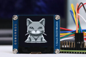
OLED display modules, particularly graphic OLED variants, are revolutionizing the way we interact with devices, offering crisp visuals, vibrant colors (in some cases), and exceptional energy efficiency.
This article delves into the intricate world of display technologies, specifically comparing OLED and LCD displays.
This article delves into the fascinating world of LCD modules, specifically focusing on their integration with Arduino and the capabilities of TFT LCD technology.
This article delves into the fascinating world of display modules, specifically focusing on LCD (Liquid Crystal Display) and TFT (Thin-Film Transistor) technology.

This article dives deep into the world of 0.96 inch OLED display modules, specifically focusing on the 128×64 resolution variant that communicates via the I2C interface.
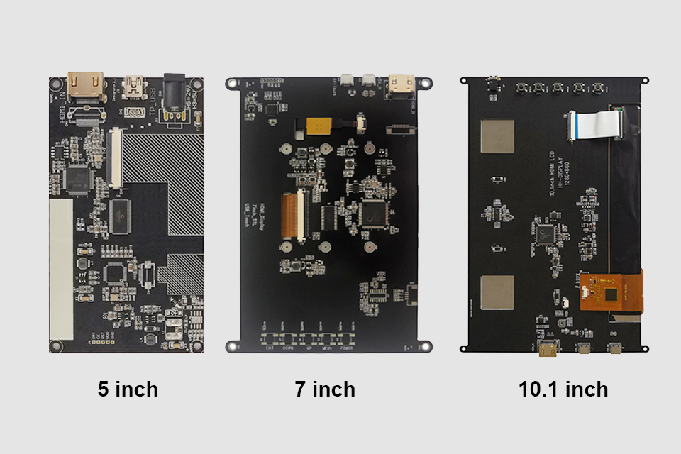
This article explores how to connect an LCD screen to a Raspberry Pi using an HDMI driver board, essentially turning your single-board computer into a miniature HDMI monitor.
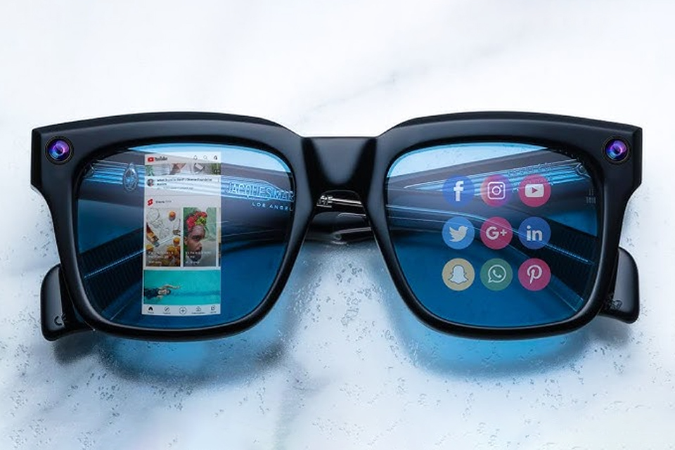
This article dives into the exciting world of augmented reality (ar) lenses, specifically focusing on the development and potential of an interchangeable lens system for ar glasses.

This article dives deep into the lifespan and durability of OLED (Organic Light Emitting Diode) displays compared to LCD (Liquid Crystal Display) screens.

@ 2025 display-module. All right reserved.
Fill out the form below, and we will be in touch shortly.