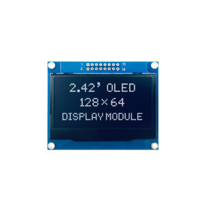
Stora saker i affärer görs aldrig av en person. De är gjorda av ett team av människor. Vi har den där dynamiska gruppen av folk
Den här artikeln fördjupar sig i kompaktens värld OLED-displaymoduler, speciellt med fokus på 0,91 tum 128×32 OLED-skärm som använder sig av I2C-gränssnitt. Vi kommer att utforska det tekniska översikt av detta svartvit visa, dess funktioner och hur den kan integreras i olika projekt, särskilt med Arduino Uno. Den här artikeln är värd att läsa eftersom den ger en omfattande förståelse för en mycket specifik och populär typ av visa teknologi. Oavsett om du är en hobby, ingenjör eller bara någon som är nyfiken på elektronik, kommer den här artikeln att utrusta dig med kunskapen för att effektivt använda dessa små men kraftfulla visas i ditt nästa projekt. Du hittar vit OLED vara mycket användbar. Vi kommer också att diskutera grunderna för 0,91 tums OLED och det är lätt att använda I2C-gränssnitt. Du kan hitta liknande modul på Vågdelning webbplats, men vi kommer att använda vår egen OLED-modul och förse dig med dedikerade handledning och stöd.
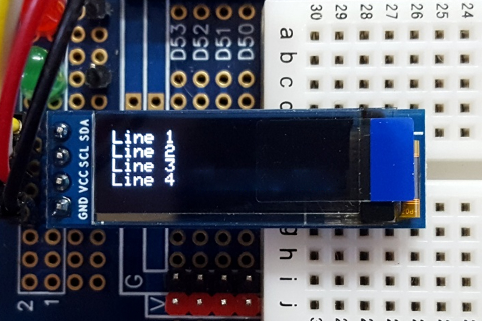
OLED-skärm Tekniken har revolutionerat hur vi interagerar med elektroniska enheter och erbjuder livfulla färger, hög kontrast, och breda betraktningsvinklar. Inom riket av OLED-skärmar, den 0.91 tum 128×32 OLED displaymodul framstår som en kompakt men ändå kraftfull lösning för projekt som kräver en liten men mycket läsbar visa. Dessa skärmarna är små, används ofta i bärbara enheter, wearables och olika inbyggda system där utrymme är en premie. 0,91 tum storlek hänvisar till diagonal mätning av visa område, medan 128×32 upplösning indikerar att visa består av 128 horisontella pixlar och 32 vertikala pixlar.
Trots sina små storlek, dessa OLED-moduler leverera skarpa och tydliga bilder, tack vare de inneboende fördelarna med OLED teknik, såsom möjligheten att stänga av individen pixlar helt, vilket resulterar i äkta svarta och hög kontrast förhållanden. Detta 0.91 128×32 svartvit OLED-modul styrs av en inbyggd styrenhet, typiskt SSD1306 drivrutin IC, vilket förenklar processen för gränssnitt visa med mikrokontroller. De SSD1306 är en OLED-drivrutin som har en inbyggd kontrollkrets. OLED-skärm är ett populärt val bland både hobbyister och proffs.
0,91 tum 128×32 OLED displaymodul är en svartvit grafisk display som packar en rad funktioner i sin kompakta formfaktor. Specifikation kan variera mellan tillverkare. En av nyckelfunktionerna i detta modul är dess OLED teknik, som tillåter var och en pixel att avge sitt eget ljus. Detta eliminerar behovet av en bakgrundsbelysning, vilket resulterar i en tunnare visa med överlägsen kontrast och lägre strömförbrukning jämfört med traditionella LCD moduler. De visa är kompatibel med många enheter.
Här är en tabell som sammanfattar det typiska specifikationer av 0,91 tum 128×32 OLED displaymodul:
| Särdrag | Specifikation |
|---|---|
| Storlek | 0.91 tum (diagonal) |
| Upplösning | 128×32 pixlar |
| Färg | Monokrom (vanligtvis vit, blå eller gul) |
| Gränssnitt | I2C (eller SPI i vissa modeller) |
| Kontroller | SSD1306 (eller kompatibel) |
| Driftspänning | 3,3V – 5V |
| Betraktningsvinkel | >160° |
| Drifttemp. | -40°C ~ 85°C |
| PCB Storlek | Varierar beroende på tillverkare |
De OLED-modul fungerar normalt vid en spänning mellan 3,3V och 5V, gör det kompatibel med ett brett utbud av mikrokontroller, inklusive Arduino brädor. Effektbehov beror på hur mycket av displayen är tänd. De gränssnitt är vanligast I2C, vilket förenklar kabeldragningen och minskar antalet input stift krävs. Vissa moduler erbjuder också en SPI gränssnitt alternativ. Kontrollera detalj angående gränssnitt på din produktsida. De SSD1306 kontroller hanterar den låga nivån detaljer av att köra OLED panel, inklusive pixel adressering, uppdateringsfrekvenser och energihantering.
De I2C (Integrerad krets) gränssnitt är ett seriellt kommunikationsprotokoll som gör att flera enheter kan kommunicera med varandra med bara två ledningar: SDA (Serial Data) och SCL (Serial Clock). Det är ett populärt val för att ansluta kringutrustning som visas, sensorer och minneschips till mikrokontroller på grund av dess enkelhet och effektivitet. De I2C-gränssnitt är särskilt väl lämpad för 0,91 tum 128×32 OLED displaymodul eftersom det minimerar antalet anslutningar som krävs, vilket är avgörande i utrymmesbegränsade applikationer.
I en I2C ställ in med OLED-modul, mikrokontrollern (t.ex. en Arduino) fungerar vanligtvis som master anordning, medan OLED-skärm fungerar som en slav anordning. Mastern initierar kommunikation och styr klocksignalen, medan slaven svarar på kommandon från mastern. Varje anordning på I2C bus har en unik 7-bitars eller 10-bitars adress, och OLED displaymodul är inget undantag. De SSD1306 kontroller används i dessa visas har en specifik I2C adress som gör att mikrokontrollern kan välja det för kommunikation. De 0,91 tums OLED är kommunicerar via I2C-gränssnitt. Fördelen med att använda I2C-gränssnitt med OLED-skärm är att det förenklar kabeldragningen, som du bara behöver ansluta två datalinjer (SDA och SCL) utöver ström och jord. Detta är särskilt fördelaktigt när man arbetar med mikrokontroller som har begränsat input/produktion stift. Dessutom, I2C tillåter flera enheter att dela samma buss, så länge som var och en anordning har en unik adress, vilket gör det enkelt att utöka ditt projekt med ytterligare sensorer eller kringutrustning.
De hårdvara av en typisk 0,91 tum 128×32 OLED displaymodul består av flera nyckelkomponenter integrerade på ett litet kretskort (PCB). Den mest framträdande komponenten är OLED panelen själv, som är en tunn, platt visa som innehåller 128×32 utbud av pixlar. De OLED panelen är vanligtvis täckt av ett skyddande glas- eller plastskikt. Du bör kontrollera skissera av din modul.
De kontroller chip, vanligtvis SSD1306, är monterad på baksidan av PCB. Detta chip ansvarar för att ta emot kommandon och data från mikrokontrollern via I2C och driva individen pixlar på OLED panel. De SSD1306 har inbyggd grafisk visa data RAM (GDDRAM) som lagrar bild data som ska visas. De storlek av detta RAM bestämmer upplösning av visa att kontroller kan stödja. För en 128×32 visa, den kontroller behöver åtminstone 512 byte RAM sedan dess varje pixel representeras av en bit (på eller av) i en svartvit visaoch 128 * 32 bitar är lika med 512 byte av data. Skärmarna är små och mycket användbar i många projekt. De PCB inkluderar även andra nödvändiga komponenter såsom motstånd, kondensatorer och spänningsregulatorer. Dessa komponenter säkerställer att OLED panel och kontroller få rätt kraft förse och driftsförhållanden. De modul har vanligtvis en rad med rubriker stift anslutningar längs ena kanten av PCB, så att du enkelt kan ansluta den till en breadboard eller mikrokontroller med hjälp av bygelkablar. Det specifika stift konfigurationen kan variera något mellan olika tillverkare men inkluderar vanligtvis stift för ström (förse), mark och I2C kommunikationslinjer (SDA och SCL).
Gränssnitt med 0,91 tum 128×32 OLED displaymodul med en Arduino Uno är en enkel process, tack vare I2C-gränssnitt och tillgängligheten av bibliotek som förenklar koda nödvändig. Här är en steg-för-steg-guide för att komma igång:
Kom ihåg att konsultera dokumentationen för det specifika bibliotek du använder för att förstå alla tillgängliga funktioner och deras användning. Med dessa enkla steg kan du snabbt få din 0,91 tum 128×32 OLED-skärm igång med en Arduino Uno.
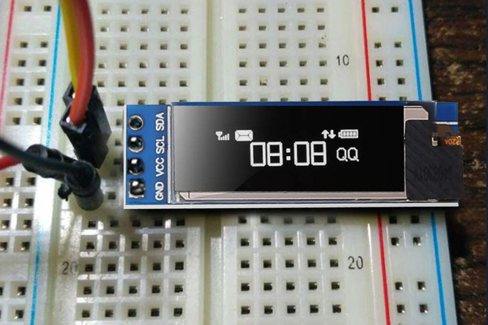
När man arbetar med OLED-displaymoduler, kommer du ofta att stöta på två vanliga seriella kommunikationsgränssnitt: SPI (Serial Perifer Gränssnitt) och I2C (Integrerad krets). Båda gränssnitten har sina fördelar och nackdelar, och valet mellan dem beror på de specifika kraven i ditt projekt.
I2C-gränssnitt:
SPI-gränssnitt:
| Särdrag | I2C | SPI |
|---|---|---|
| Ledningar | 2 (SDA, SCL) | 4+ (MOSI, MISO, SCK, CS per enhet) |
| Hastighet | Långsammare (vanligtvis 100 kHz – 1 MHz) | Snabbare (vanligtvis flera MHz eller mer) |
| Adressering | Enhetsadress | Chip Select (CS) linje per enhet |
| Energiförbrukning | Lägre | Högre |
| Komplexitet | Enklare ledningar, mer komplext protokoll | Mer komplex ledning, enklare protokoll |
| Användningsfall | Lägre datahastigheter, flera enheter på bussen | Höga datahastigheter, färre enheter, snabbare uppdateringar |
För den 0.91 tum 128×32 OLED displaymodul, den I2C-gränssnitt är ofta det föredragna valet på grund av dess enkelhet och lägre antal stift. Men om ditt projekt kräver mycket snabbt visa uppdateringar eller om du redan använder SPI för andra komponenter, använd sedan en SPI version av OLED-modul kanske passar bättre.
För att kontrollera 0,91 tum 128×32 OLED displaymodul från en mikrokontroller som Arduino Uno, måste du använda en programvara bibliotek som tillhandahåller en uppsättning funktioner för att skicka kommandon och data till visa. Flera bibliotek finns att arbeta med SSD1306-baserad OLED-skärmar, med två av de mest populära är Adafruit SSD1306 bibliotek och U8g2 bibliotek.
Adafruit SSD1306 bibliotek är speciellt utformad för svartvit OLED-skärmar som använder SSD1306 kontrollerinklusive 0,91 tum 128×32 modul. Det tillhandahåller ett enkelt och lättanvänt API för att initiera visa, ritning grundläggande former och visning text. De bibliotek är byggd ovanpå Adafruit GFX bibliotek, som tillhandahåller en gemensam uppsättning grafikfunktioner som fungerar över olika typer av visas.
Här är en koda exempel som visar hur man initierar visa och visa några text använder Adafruit SSD1306 bibliotek:
    #omfatta <SPI.h>
    #omfatta <Wire.h>
    #omfatta <Adafruit_GFX.h>
    #omfatta <Adafruit_SSD1306.h>

    #definiera SCREEN_WIDTH 128 // OLED-skärmens bredd, i pixlar
    #definiera SCREEN_HEIGHT 32 // OLED-skärmens höjd, i pixlar

    // Deklaration för ett I2C-gränssnitt
    #definiera OLED_RESET 4 // Återställ stift # (eller -1 om du delar Arduino återställningsstift)
    #definiera SCREEN_ADDRESS 0x3C ///< Se datablad för Adress; 0x3D för 128x64, 0x3C för 128x32
    Adafruit_SSD1306 visa(SCREEN_WIDTH, SCREEN_HEIGHT, &Tråd, OLED_RESET);

    ogiltig inställning() {
      Serie.börja(9600);

      // SSD1306_SWITCHCAPVCC = generera displayspänning från 3,3V internt
      om(!visa.börja(SSD1306_SWITCHCAPVCC, SCREEN_ADDRESS)) {
        Serie.println(F("SSD1306-allokering misslyckades"));
        för(;;); // Fortsätt inte, loop för alltid
      }

      // Visa initial visningsbuffertinnehåll på skärmen --
      // biblioteket initierar detta med en Adafruit-startskärm.
      visa.visa();
      dröjsmål(2000); // Pausa i 2 sekunder

      // Rensa bufferten
      visa.clearDisplay();

      // Rita en enda pixel i vitt
      visa.drawPixel(10, 10, SSD1306_WHITE);

      // Visa visningsbufferten på skärmen. Du MÅSTE anropa display() efter
      // ritkommandon för att göra dem synliga på skärmen!
      visa.visa();
      dröjsmål(2000);
      // display.display() är INTE nödvändigt efter varje enskilt ritkommando,
      // om det inte är vad du vill...snarare kan du samla ihop en massa
      // ritoperationer och uppdatera sedan skärmen på en gång genom att ringa
      // display.display(). Dessa exempel visar båda tillvägagångssätten...

      testdrawline();      // Rita många linjer

      testdrawrect();      // Rita rektanglar (konturer)

      testfillrect();      // Rita rektanglar (fyllda)

      testdrawcircle();    // Rita cirklar (konturer)

      testfillcircle();    // Rita cirklar (fyllda)

      testdrawroundrect(); // Rita rundade rektanglar (konturer)

      testfillroundrect(); // Rita rundade rektanglar (fyllda)

      testdrawtriangle();  // Rita trianglar (konturer)

      testfilltriangle();  // Rita trianglar (fyllda)

      testdrawchar();      // Rita tecken i standardteckensnittet

      testdrawstyles();    // Rita "stiliserade" karaktärer

      testscrolltext();    // Rita rullande text

      testdrawbitmap();    // Rita en liten bitmappsbild

      // Invertera och återställa displayen, pausa däremellan
      visa.invertDisplay(true);
      dröjsmål(1000);
      visa.invertDisplay(false);
      dröjsmål(1000); testanimate(logo_bmp, LOGO_WIDTH, LOGO_HEIGHT); // Animera bitmappar
    }
U8g2 bibliotek är en mer omfattande bibliotek som stöder ett brett utbud av svartvit visas, inklusive OLED, LCD-skärmar och e-papper visas. Den erbjuder mer avancerade funktioner än Adafruit SSD1306 bibliotek, såsom stöd för flera teckensnitt, Unicode-tecken och olika ritning operationer.
Både bibliotek är väldokumenterade och kommer med exempelskisser som visar hur man använder de olika funktionerna. Du kan hitta dessa exempel i Arduino IDE under Arkiv > Exempel efter installation av bibliotek. Du kan ladda ner både bibliotek från internet.
Skapa grafik och visa bilder på 0.91 tum 128×32 OLED-skärm innebär att man använder de funktioner som tillhandahålls av visa bibliotek att manipulera individen pixlar eller rita fördefinierade former. De specifika teknikerna du använder beror på komplexiteten hos den grafik du vill skapa och kapaciteten hos bibliotek du använder.
Grundläggande ritning:
Det mest grundläggande ritning operation ställer in färgen på individen pixlar. Du kan använda drawPixel(x, y, färg) funktion för att vända en specifik pixel på eller av (i fallet med en svartvit visa). Genom att kombinera flera drawPixel samtal kan du skapa enkla former och mönster.
De visa bibliotek även tillhandahålla funktioner för ritning grundläggande former som linjer, rektanglar och cirklar. Till exempel Adafruit GFX bibliotek erbjuder funktioner som drawLine(), drawRect(), fillRect(), drawCircle(), och fillCircle(). Dessa funktioner tar parametrar som start- och slutkoordinater, bredd och höjd (för rektanglar), radie (för cirklar) och färgen.
Textvisning:
Visar text på OLED är ett vanligt krav för många projekt. De visa bibliotek tillhandahåller vanligtvis funktioner för att ställa in teckensnittet, storlek, och färgen på text, samt att placera markören och skriva ut strängar till visa.
Adafruit GFX bibliotek, till exempel, innehåller ett standardteckensnitt och låter dig välja olika teckenstorlekar med hjälp av setTextSize(). Du kan ställa in markörens position med setCursor(x, y) och skriva ut text använder skriva ut() eller println(). U8g2 bibliotek erbjuder mer avancerade text hanteringsmöjligheter, inklusive stöd för flera teckensnitt och Unicode-tecken.
Bildskärm:
Visar bitmapp bilder på OLED kräver att konvertera bild data till ett format som visa kontroller kan förstå. Detta innebär vanligtvis att skapa en array av byte där varje bit representerar en pixel på visa. För den 128×32 OLED, du skulle behöva en mängd 512 byte (128 * 32 / 8 = 512).
Du kan använda specialiserade mjukvaruverktyg för att konvertera bild fil till lämplig bitmapp formatera. När du väl har bitmapp data kan du använda en funktion som drawBitmap() (tillhandahålls av vissa bibliotek) för att visa bild på OLED. Du måste ange startkoordinaterna, bredden och höjden på bild, och bitmapp array.
Här är ett exempel på hur du kan definiera en enkel bitmapp för en hjärtform och visa den med Adafruit SSD1306 bibliotek:
    static const unsigned char PROGMEM heart_bmp[] = { 0b00000000, 0b00000000,
      0b00000110, 0b01100000,
      0b00001111, 0b11110000,
      0b00011111, 0b11111000,
      0b00111111, 0b11111100,
      0b00111111, 0b11111100,
      0b01111111, 0b11111110,
      0b01111111, 0b11111110,
      0b00111111, 0b11111100,
      0b00011111, 0b11111000,
      0b00001111, 0b11110000,
      0b00000111, 0b11100000,
      0b00000011, 0b11000000,
      0b00000001, 0b10000000,
      0b00000000, 0b00000000
    }; // I din huvudslinga eller en funktion:
    visa.drawBitmap(50, 0, heart_bmp, 16, 16, 1);
    visa.visa();
Tänk på att 0,91 tum 128×32 OLED har begränsat minne och en relativt låg upplösning. Komplexa bilder kan behöva förenklas eller skalas ner för att passa inom dessa begränsningar.
När du arbetar med 0.91 tum 128×32 OLED displaymodul, är det viktigt att tänka på kraften förse krav för att säkerställa korrekt drift och undvika att skada visa. OLED-skärmar är i allmänhet mer energieffektiva än traditionella LCD eftersom de inte kräver en bakgrundsbelysning. Strömförbrukningen kan dock fortfarande variera beroende på faktorer som t.ex ljusstyrka inställning, antalet pixlar som är upplysta, och det specifika OLED teknik som används.
0,91 tum 128×32 OLED-modul fungerar normalt vid en spänning mellan 3,3V och 5V. De flesta moduler är designade för att vara kompatibel med både 3,3V och 5V logiknivåer, vilket gör dem mångsidiga för användning med olika mikrokontroller. Det är viktigt att kontrollera specifikation ark för din specifika modul för att bestämma den rekommenderade driftspänningen. Det faktiska effektbehovet beror på hur mycket av displayen lyser vid varje given tidpunkt. När alla pixlar är avstängda, de visa drar väldigt lite ström. När alla pixlar är påslagna, de skärmen använder cirka 20mA på genomsnittet som skärmen använder cirka 20-25 mA ström vid full ljusstyrka. Men om bara en liten del av visa lyser blir strömdragningen betydligt lägre.
För att driva OLED-modul, kan du vanligtvis ansluta VCC-stiftet till 3,3V eller 5V förse stift på din mikrokontroller. Om du använder en Arduino Uno, till exempel kan du ansluta VCC stift till 5V stift på Arduino. Några OLED-moduler har inbyggda spänningsregulatorer som gör att de kan acceptera ett bredare utbud av input spänningar.
Det är viktigt att notera att medan OLED-skärmar är relativt strömsnåla, kan de fortfarande dra en betydande mängd ström när de visar ljusa bilder eller när en stor del av skärm lyser upp. Om du designar en batteridriven enhet måste du ta hänsyn till detta när du beräknar din energibudget och väljer ett batteri.
För att optimera strömförbrukningen kan du justera ljusstyrka av visa använda kommandon som tillhandahålls av visa bibliotek. Många bibliotek låter dig ställa in kontrast eller ljusstyrka nivå, vilket påverkar det totala strömdraget. Sänker ljusstyrka kan avsevärt minska strömförbrukningen, särskilt när du visar övervägande mörkt innehåll.
För att effektivt använda 0,91 tum 128×32 OLED displaymodul i dina projekt är det viktigt att ha tillgång till det relevanta teknisk dokumentation, datablad, koda prover och andra resurser. Dessa resurser ger värdefull information om displayens specifikationer, pinout, gränssnitt, kontrolleroch programmering.
Det viktigaste dokumentet är databladet för OLED displaymodul sig. Detta datablad tillhandahålls vanligtvis av tillverkaren och innehåller detaljerad information teknisk information om visa, inklusive:
Du kan vanligtvis hitta databladet för din specifika OLED-modul på tillverkarens webbplats eller webbplatsen för återförsäljaren där du köpte visa. Några populära tillverkare av OLED-displaymoduler inkluderar Adafruit, Waveshare och olika kinesiska tillverkare vars produkter säljs via onlinemarknadsplatser som AliExpress och Banggood.
Utöver databladet behöver du också dokumentationen för bibliotek du använder för att kontrollera visa. Till exempel, om du använder Adafruit SSD1306 bibliotek, kan du hitta dokumentationen på Adafruit-webbplatsen eller GitHub-förrådet för bibliotek. Dokumentationen innehåller vanligtvis en beskrivning av tillgängliga funktioner, exempel koda, och detaljer om hur man installerar och använder bibliotek.
Här är några användbara länkar för att hitta resurser relaterade till 0.91 tum 128×32 OLED displaymodul:
Kom ihåg att konsultera dokumentationen för ditt specifika OLED-modul och bibliotek, eftersom det kan finnas variationer i funktioner, pinouts och kommandon mellan olika tillverkare och versioner. Det är klokt att klick på några länkar och gör ordentlig research innan du startar ett projekt.
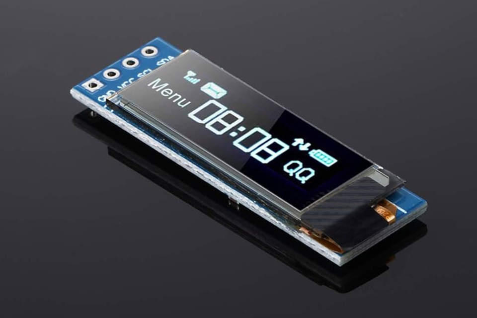
drawPixel(), medan mer komplexa former kan ritas med funktioner som drawLine(), drawRect(), och drawCircle().drawBitmap() för att överföra uppgifterna till displayens minne.Genom att förstå dessa viktiga takeaways kommer du att vara väl rustad att införliva 0,91 tum 128×32 OLED displaymodul in i ditt nästa elektronikprojekt och lägg till en skarp och kompakt bild gränssnitt till dina skapelser. Kom ihåg att du kan hitta användbara handledning online kan vi också förse dig med stöd om du behöver det.
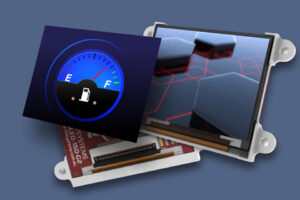
AMOLED-displaymoduler håller snabbt på att bli guldstandarden inom visuell teknik, och erbjuder oöverträffad bildkvalitet, livfulla färger och exceptionell energieffektivitet.
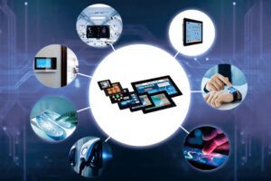
Den här artikeln fördjupar sig i den fascinerande världen av displaymoduler, speciellt med fokus på LCD (Liquid Crystal Display) och TFT (Thin-Film Transistor)-teknik.

Världen av virtuell verklighet (VR) och förstärkt verklighet (AR) utvecklas snabbt, och i hjärtat av denna transformation ligger en kritisk komponent: displayen.

This article dives deep into the lifespan and durability of OLED (Organic Light Emitting Diode) displays compared to LCD (Liquid Crystal Display) screens.
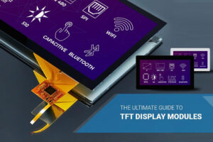
Den här artikeln är din omfattande guide för att förstå och navigera i världen av byte av LCD-skärmmoduler.
Stora saker i affärer görs aldrig av en person. De är gjorda av ett team av människor. Vi har den där dynamiska gruppen av folk
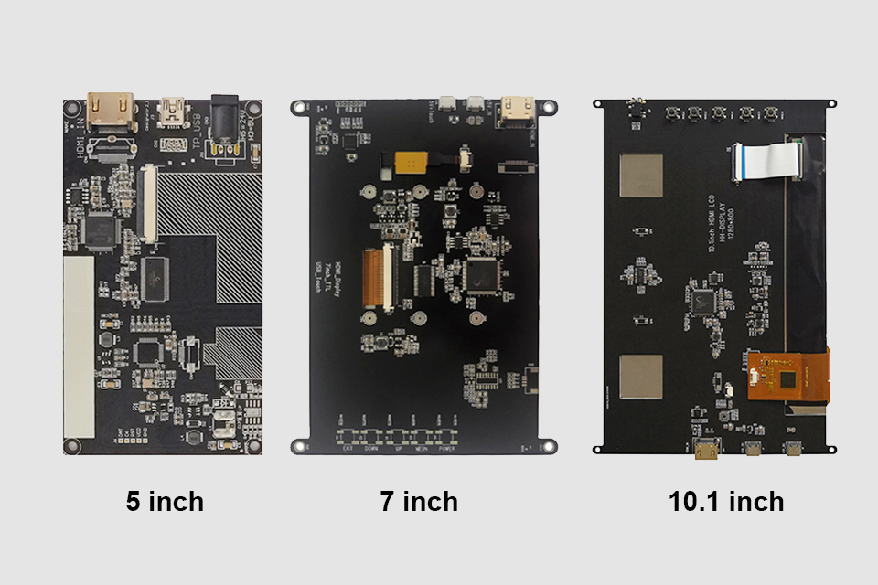
This article explores how to connect an LCD screen to a Raspberry Pi using an HDMI driver board, essentially turning your single-board computer into a miniature HDMI monitor.
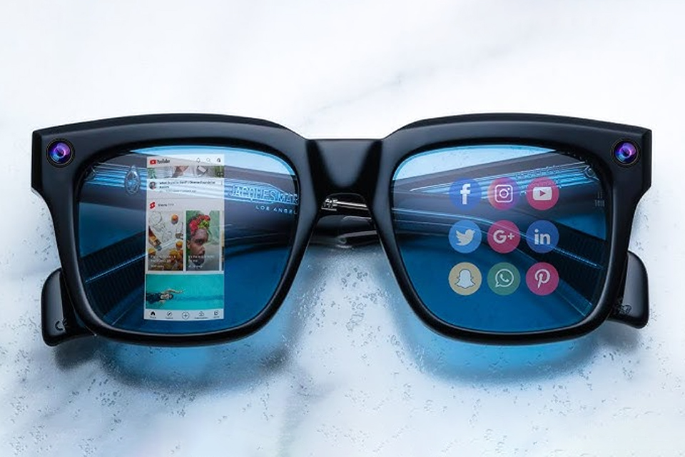
This article dives into the exciting world of augmented reality (ar) lenses, specifically focusing on the development and potential of an interchangeable lens system for ar glasses.

This article dives deep into the lifespan and durability of OLED (Organic Light Emitting Diode) displays compared to LCD (Liquid Crystal Display) screens.

@ 2025 display-modul. Alla rättigheter reserverade.
Fyll i formuläret nedan så hör vi av oss inom kort.