
Great things in business are never done by one person. They’re done by a team of people. We have that dynamic group of peoples
The 16×2 LCD module, a cornerstone of embedded systems, is a fantastic tool for displaying textual information. This article dives deep into the workings of this versatile display, exploring its pin configuration, how to interface it with an Arduino, and even how to create custom characters. If you’re looking to add a clear, readable display to your Arduino projects, this guide is an essential resource.
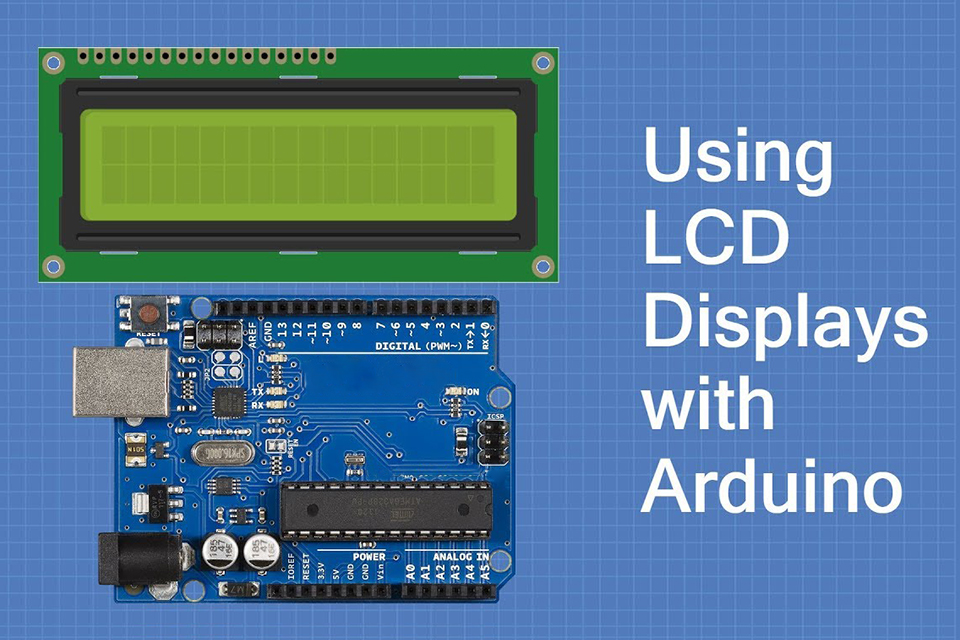
An LCD, or liquid crystal display, is a flat panel display technology commonly used in a wide array of devices, from watches and calculators to computer monitors and televisions. The 16×2 LCD module is particularly popular for hobbyists and embedded system developers because of its simplicity, low cost, and the ability to display textual information clearly. Unlike more complex graphic displays, the 16×2 lcd is designed for character-based output. The “16×2” designation means it has 2 lines, each capable of displaying 16 characters at a time. This makes it ideal for displaying sensor readings, menu options, or any form of text data. This type of display is a character lcd that is extremely widely used in various projects. The 16×2 lcd module is a type of display module that doesn’t require complex programming to use. It also uses very little power, making it suitable for battery-powered applications.
The wide availability and cost-effectiveness of the 16×2 display module make it a popular choice for educational projects and small-scale applications. The ease of interfacing with microcontrollers like Arduino, combined with a broad range of libraries available, makes it a go-to choice for beginners and experienced users. This type of lcd module is often used as a character lcd and is known for its reliability and simple operation. The display using this kind of module is very clear. The 16×2 character lcd allows to show 16 characters per line.
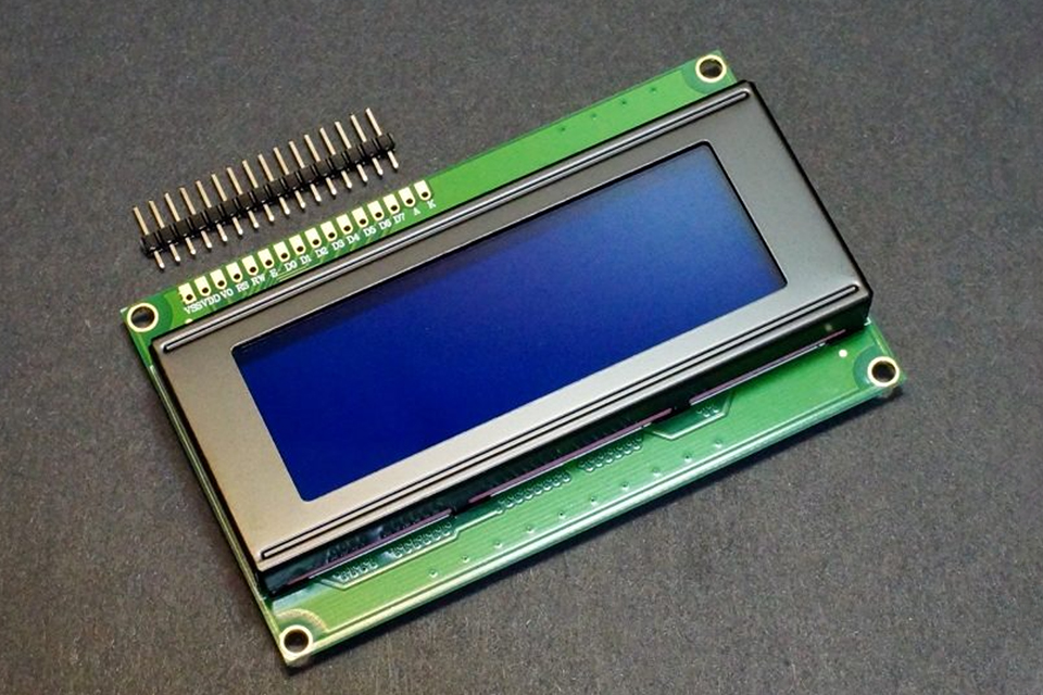
The 16×2 lcd module typically comes with 16 pins, each serving a specific purpose. Understanding the lcd pinout is crucial for successful interfacing. Here’s a breakdown of each pin:
This detailed explanation of the lcd pinout is key to understanding the interface. Correct pin connections are essential for proper functioning of the lcd display. For an illustration of the pinout refer to Table 1.
Table 1: 16×2 LCD Pinout
| Pin Number | Symbol | Description |
|---|---|---|
| 1 | VSS | Ground (0V) |
| 2 | VDD | +5V Power Supply |
| 3 | V0/VEE | Contrast Adjustment |
| 4 | RS | Register Select |
| 5 | R/W | Read/Write Select |
| 6 | E | Enable Signal |
| 7 | D0 | Data Bit 0 |
| 8 | D1 | Data Bit 1 |
| 9 | D2 | Data Bit 2 |
| 10 | D3 | Data Bit 3 |
| 11 | D4 | Data Bit 4 |
| 12 | D5 | Data Bit 5 |
| 13 | D6 | Data Bit 6 |
| 14 | D7 | Data Bit 7 |
| 15 | A | LED Backlight Anode |
| 16 | K | LED Backlight Cathode |
The 16×2 lcd module uses a liquid crystal display (LCD) technology to display characters. Each character on the lcd is composed of a grid of pixels. These pixels are not individually controlled by the user but are controlled by the lcd chip controller. The module has a built-in character generator which stores predefined shapes for the standard ascii character set. When you send a character code to the display, the controller fetches the pixel configuration from its character generator and displays the character on the lcd screen.
The communication between the microcontroller and the lcd is achieved by sending commands and data. Commands are used to control the display’s behavior, such as clearing the display, moving the cursor, or setting the display mode. Data are the characters you want to display. The lcd module uses the pins previously described to receive data and commands. The lcd chip controller is responsible for interpreting and executing those instructions. The controller also manages the cursor position and the display of characters based on the address sent with the data. This allows a microcontroller to send data to the lcd and have it displayed.
While the 16×2 lcd is very common, other types of LCD modules exist, each with specific characteristics. Here are some differences to consider:
When selecting an lcd module, consider the complexity and type of information that you want to display. For basic text output, the 16×2 character lcd remains a reliable and cost effective option. Understanding what type of display and what type of interface is required is key in selecting the correct display module.
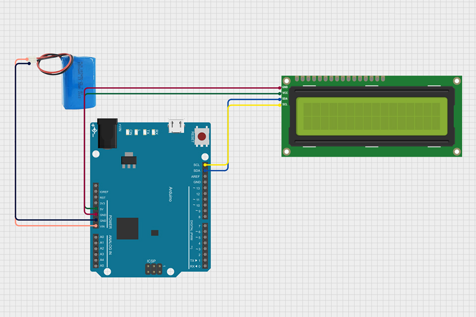
Interfacing a 16×2 lcd with an arduino is a straightforward process, especially with the use of libraries. Here’s a step-by-step guide for connecting and displaying basic text:
Wiring:
Arduino Code: Install the LiquidCrystal library within the Arduino IDE, and then use code similar to the following:
#include <LiquidCrystal.h>

const int rs = 12, en = 11, d4 = 5, d5 = 4, d6 = 3, d7 = 2;
LiquidCrystal lcd(rs, en, d4, d5, d6, d7);

void setup() {
  lcd.begin(16, 2);
  lcd.print("Hello, World!");
}

void loop() {
  // Your other code can be included here, LCD will keep displaying the message
}
This simple example demonstrates the basics of interfacing with arduino and displaying data on the lcd. This also demonstrates how to use the lcd in 4-bit mode to simplify the number of pins used.
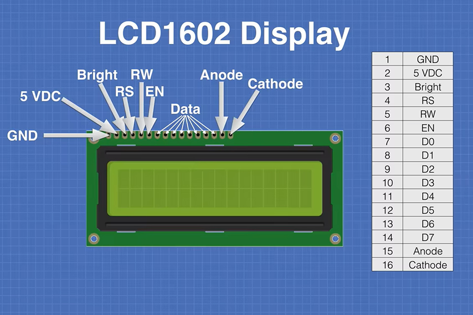
Sending data and commands to the lcd is essential to control its behavior and display information. As previously mentioned, the RS pin is used to differentiate between data and commands. When RS is low, instructions given to the lcd are considered commands; when it is high, they are treated as data, which is typically a character to be displayed.
Sending Commands: To send commands, first set the RS pin low. The instructions can include actions like clearing the display, setting cursor position, or configuring the display mode. The send commands are typically used to configure the lcd for operation. The library methods used with arduino will handle all that.
Sending Data: To send data, set the RS pin high. The data sent will be interpreted as an ascii code of the character to be displayed. Each character has an associated code, which can be found in the standard ascii character set. The lcd then retrieves the corresponding character from its character generator and shows it on the screen. The process is handled by the library but it is useful to know the basic functionality. In order for the data to be written to the lcd, the data pins have to be set.
The library functions, such as lcd.print() automatically handle the complexity of controlling the RS and E pins, as well as sending the correct byte to the lcd. This significantly simplifies the process of sending data to the lcd. It is also possible to send commands using the library methods, for example, lcd.clear() is used to clear the display and lcd.setCursor() is used to set the current cursor position on the display.
The backlight of a 16×2 lcd is very useful in poor light conditions. Most of 16×2 display modules include an led backlight. To control the backlight you need to power the anode (pin 15) and cathode (pin 16) pins, usually via a resistor. There are a few ways that the backlight can be controlled. You can simply connect the backlight directly to the power and ground, in this case, the backlight will be permanently turned on. If you are using this method it’s highly recommended to include a current limiting resistor in series with the anode pin. To control the backlight with the microcontroller you need to connect anode (pin 15) to one of the pins of the arduino and the cathode (pin 16) to the ground. By setting the output of the pin to high or low, you will be able to turn the backlight on or off.
Using a pin of arduino to control the backlight makes it possible to turn it off if it is not needed or implement other features like for example: fading the backlight on and off. You should always check the datasheet for the maximum backlight current to choose the correct resistor. Typically a 220 Ohm resistor will work fine. When the pin is set to high, the led backlight will be on, otherwise it will be off. Controlling the backlight in code will help to save power if the backlight is not needed.
Adjusting the contrast is crucial for achieving optimal readability of the lcd display. The contrast of the lcd is adjusted by changing the voltage applied to the V0 or VEE pin (pin 3). This voltage controls the contrast of the pixels. In order to adjust the contrast of the display, a potentiometer is typically connected to this pin. When you rotate the potentiometer, the voltage on this pin changes. If the voltage is too high, the display will be black, and if the voltage is too low the display will be barely visible. In order to adjust the contrast you have to find a point that is good for the particular lcd.
By connecting a potentiometer it’s easy to manually adjust the contrast of the display. This is a very common method. The process of adjusting the contrast involves slowly rotating the potentiometer until the characters become clearly visible. If your display shows only black blocks or is very dim, it means that the contrast is not correctly adjusted. The contrast of the display may change when the temperature changes. A small adjustment might be necessary after some time of usage. This method is cheap and it works effectively. Adjusting the contrast of the lcd is needed to achieve optimal visibility.
The ability to define and display custom characters significantly enhances the versatility of a 16×2 lcd. The built-in character generator already stores a predefined set of standard ascii character set, however the user can overwrite 8 locations in the custom character memory. Custom character generation on the display is achieved by creating a byte pattern for every custom character. Each character is defined using 5×8 pixel matrix, which means there are 5 bits per row and 8 rows. This means we need 8 bytes of data to define the custom character.
Steps to Generate and Display a Custom Character:
lcd.createChar() method to store the bytes in the character generator memory of the lcd. The createChar method takes two parameters: the location in the character generator memory (0-7) and the byte array.lcd.write() with the character location (0-7). Here’s an example of creating and displaying a custom character using Arduino: “`arduino #include LiquidCrystal lcd(12, 11, 5, 4, 3, 2);byte customChar[8] = { 0b00000, 0b01010, 0b01010, 0b10001, 0b01110, 0b00000, 0b00000, 0b00000 };
void setup() { lcd.begin(16, 2); lcd.createChar(0, customChar); lcd.write(0); }
void loop() {} “` This code will create a custom character at location 0 and display it in the first position on the lcd screen. When you are creating your custom character, you have to be careful and use the character generator addresses and printing commands in a correct way.
While 16×2 lcd modules are generally reliable, certain issues may arise. Understanding these issues and knowing how to address them can save significant time and effort:
clear() command.Proper debugging techniques, such as checking each connection step-by-step, can help to diagnose these problems. Ensure that the correct libraries are installed and the arduino board is working correctly. Double checking the connections to the lcd and the pins of the arduino is very important. When working with the LCD in 4-bit mode, ensure that you have used the correct data pins (D4-D7) and the data is sent correctly by the library functions.
By understanding the workings of the 16×2 lcd and following these guidelines, you can effectively integrate this versatile display into your arduino projects.
This article delves into the world of compact OLED display modules, specifically focusing on the 0.91 inch 128×32 OLED display that utilizes the I2C interface.

This article dives deep into the fascinating world of microdisplays, focusing specifically on the groundbreaking 4K OLED technology developed by Sony Semiconductor Solutions.
This article explores the fascinating world of Organic Light Emitting Diode (OLED) display modules, with a particular focus on graphic OLED displays.
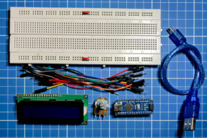
Liquid Crystal Displays (LCDs) are ubiquitous in modern technology, from our smartphones to our televisions.
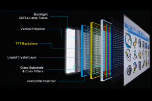
This article dives into the world of displays, specifically focusing on LCD technology.

The world of virtual reality (VR) and augmented reality (AR) is rapidly evolving, and at the heart of this transformation lies a critical component: the display.

This article dives deep into the fascinating world of microdisplays, focusing specifically on the groundbreaking 4K OLED technology developed by Sony Semiconductor Solutions.
This article dives deep into the world of interfacing a 16×2 LCD module with microcontrollers like Arduino and ESP32, specifically focusing on the setup without using an I2C module.

@ 2025 display-module. All right reserved.
Fill out the form below, and we will be in touch shortly.